Creating HDL Descriptions for ASIC and FPGA Designs
Whether you are working with VHDL or Verilog, you will find that hardware description languages are different from sequential programming languages because VHDL and Verilog are parallel languages specified for modelling hardware. As a rule, the design flow in hardware development for FPGA and ASIC components consists of input, simulation, synthesis, place & route, and validation of the chips.
At the beginning of the development process in hardware development there is the HDL code description. There are several basic decisions to be made here:
- What language (VHDL, Verilog, System Verilog, SystemC)?
- Should it be a monolingual design or a mixed-language design (e.g. VHDL for the own blocks and Verilog for IP blocks of the FPGA manufacturers)?
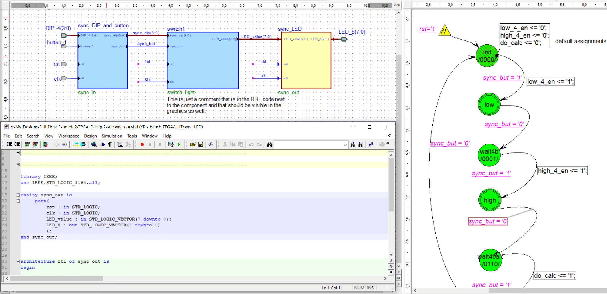
- Are all blocks described textually or should a graphic tool also be used?
We would be happy to help you evaluate the advantages and disadvantages. Simply contact us at support@evision-systems.de and we will get in touch with you.
You can find more information about the different input tools on our HDL Design page.
Verifying HDL code in hardware development
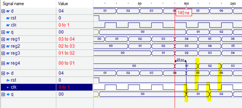
To find errors in the design in time, there are several verification methods. First, static methods can determine whether the code is written correctly in terms of syntax and semantics and whether there are structural problems within the code. However, functional aspects cannot usually be taken into account here.


