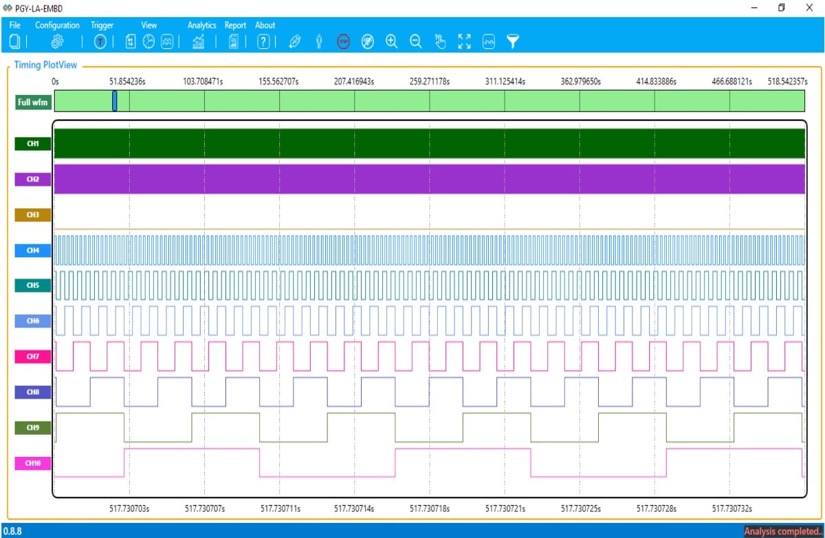
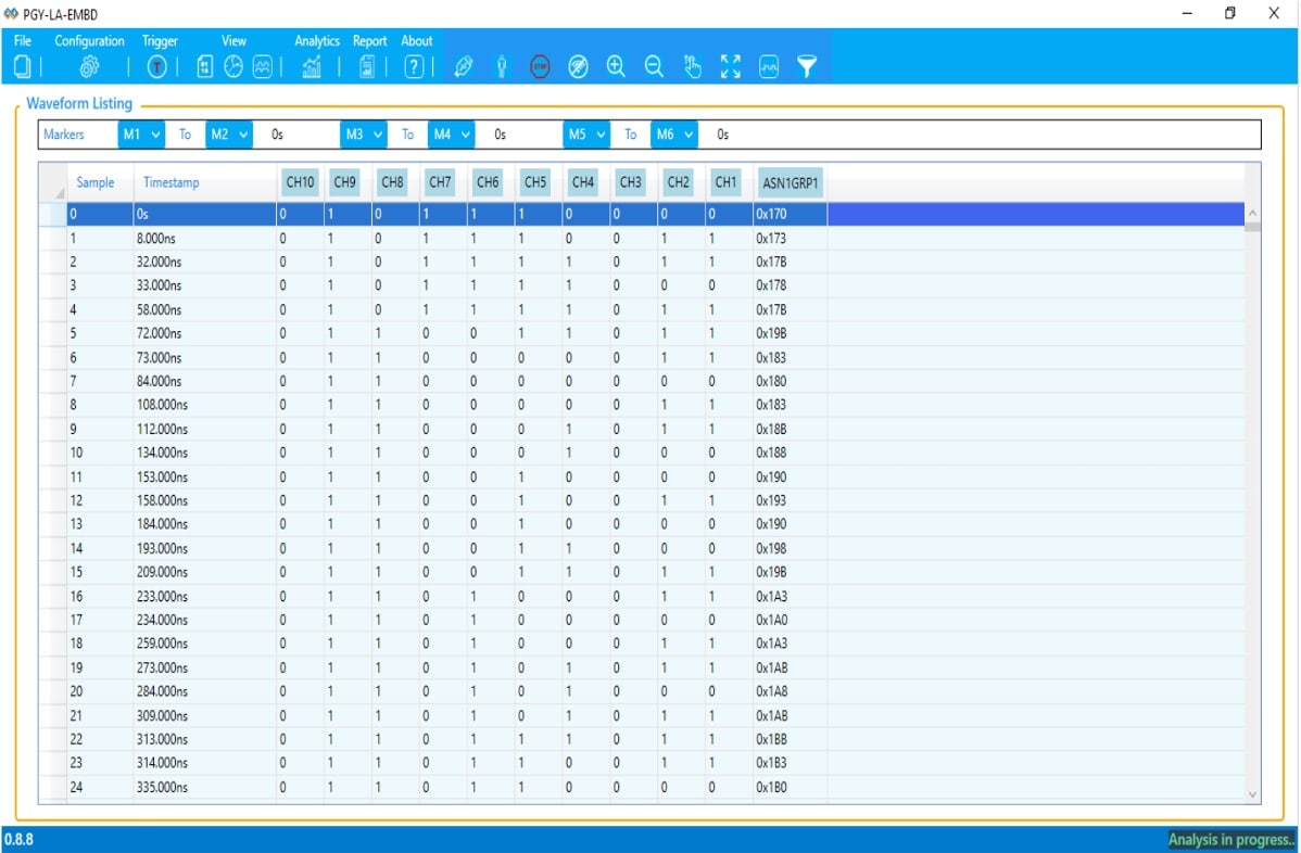
A logic analyzer is an electronic measurement device that captures and displays multiple signals from a digital design. It is an excellent tool for checking and debugging ICs, digital systems, circuits such as embedded systems, electronic control units, computers, etc. A modern logic analyzer can convert the captured data into timing diagrams, protocol decodes, state machine traces, and assembly language.
Timing View

Statemachine view

Protocol view

During software/hardware integration, logic analyzers track the execution of the embedded software and analyze the performance of the programs. Some logic analyzers can also correlate source code with specific hardware activity in your design.
Basic use of a logic analyzer:
Troubleshoot and verify the operation of digital systems.
Track and correlate many digital signals simultaneously.
Erkennen und Analysieren von Timing-Verletzungen und Störungen auf Bussen.
Track the execution embedded software.
Troubleshooting microprocessor-based designs requires more inputs than most conventional analog oscilloscopes can provide. A typical logic analyzer has 8 or more channels and is particularly useful for studying the timing of digital signals or data on a bus. For example, an address, data or control bus of a microprocessor. They can decode the information on microprocessor buses and display it in a descriptive way.

A logic analyzer measures and analyzes signals differently than an oscilloscope. The logic analyzer does not measure analog data. Instead, it recognizes logical thresholds. When a logic analyzer is connected to a digital circuit, only two logic states of the signal are of interest. So a logic analyzer looks for two logic levels only. When the input is above the threshold voltage (V), the level is called a “high” or “1”; conversely, the level below Vth is a “low” or “0”. If a logic analyzer samples the input, it will store a “1” “true” or a “0” “false” depending on the level of the signal relative to the voltage threshold.
Historical development of the logic analyzer
After the invention of the integrated circuit (IC) in the early 1960s, circuits became smaller and smaller. As the technology continued to evolve over the years, so did the processing power and speed of the IC’s. For this reason, testing and debugging electronic devices proved difficult as thousands and millions of transistors could be placed in a single chip, reducing their overall size and increasing the number of pins. Therefore, logic analyzers proved to be an important tool for electronic circuit analysis because they could temporally correlate a large number of signals on a single display, which made it easier to observe data movement and processing in many embedded systems or in the periphery of small computer systems.
Hewlett Packard announced in 1973 the invention of the first logic analyzer capable of measuring and displaying logic states via a series of LEDs. The HP 5000A was the first commercially available logic analyzer and had two channels.
What are the different types of logic analyzers?
There are three different forms of logic analyzers: modular logic analyzers, portable logic analyzers, and PC-based logic analyzers. Each form factor has its advantages and disadvantages.
Modular logic analyzers
Modular logic analyzers are composed of a chassis or mainframe and logic analyzer modules. The housing contains the display and control elements, the computer and several slots in which the actual measurement hardware is installed. The modules each have a certain number of channels, of which you can also connect very many modules to achieve a very high number of channels. They are among the more expensive devices and offer the user a high level of functionality due to the high number of channels.
Portable logic analyzers
Portable logic analyzers (stand-alone logic analyzers) are more mobile than modular logic analyzers because they consist of one device including a screen. In general, they are less conductive than the modular logic analyzers.
PC-based logic analyzers
PC-based logic analyzers are compact and connect directly to a computer via an Ethernet or USB cable. This makes them cheaper because they use the existing keyboard, screen and processing power of the PC. However, they have lower performance compared to modular and portable logic analyzers.
Different analysis views
With modern logic analyzers, it is possible to perform time and state analysis simultaneously. This has the advantage that you only have to measure once and the results correlate. If you have found an error in the state analysis, you can check in the time analysis whether a fault such as a glitch can be found. Optimally, protocol analysis is also integrated in the logic analyzer, so that errors can also be found quickly at system or bus level.
Time analysis (asynchronous measurement, timing analysis)
The signals are recorded and stored with an internal clock signal. In this analysis mode, the logic analyzer behaves like an oscilloscope with an amplitude resolution of one bit per channel.
In this general form, the horizontal axis represents time and the vertical axis represents stress amplitude. The respective display is in the time domain, since the waveforms of both instruments are time-dependent. This is called “asynchronous” measurement because the internal clock runs asynchronously to the tested system.
State analysis (synchronous measurement, state analysis)
State analysis, also known as synchronous measurement or state analysis, is a method for investigating and analyzing electronic systems. The times at which the data is scanned and stored are determined by a clock signal. This clock signal comes directly from the DUT (test object), i.e. the object to be analyzed itself.
The data is recorded specifically when the specified edge (high-low / low-high) of the clock signal occurs. In addition, the associated qualifier signals must be valid. These signals are certain conditions or parameters that must be met in order to start recording.
The great advantage of this method is that only the processes that are really of interest are recorded. This prevents unnecessary or irrelevant data from being collected, which simplifies and speeds up the analysis process.
To implement this method, a signal from the circuit to be tested is used. An external clock, a kind of timer or counter, determines when the logic signal is to be saved. This timing is crucial to ensure that the relevant data is recorded and stored correctly.
Overall, the status analysis enables an efficient and targeted investigation of embedded systems by concentrating data acquisition on the really relevant processes.
Protocol analysis (I2C, I3C, SPI, UART, RFFE, CAN, SPMI)
During protocol analysis, the decoded packet information in each state and all packet details are
with error information displayed in the packages. This provides insight at the system level. Selected frames can then be automatically correlated with the timing view to see the timing information of the packet.
Logic and protocol analyzer for embedded systems
PGY-LA-EMBD is the first logic analyzer that allows you to debug timing issues while performing protocol analysis of I2C, SPI, UART or I3C, SPMI and RFFE. This allows problems to be debugged and found quickly at the circuit and system level.

